GOES-17 Satellite Imagery
I had seen some cool pictures online of images obtained using a SDR from GOES-17, a geostationary weather satellite over the west coast of the US. There is also a complementary GOES-16 over the east coast. There are also a few other similar satellites from different countries, in different locations, and different communication protocols. Due to the quarantine for COVID-19, now seemed like a good time to stay at home and point a dish at the sky with hopes of receiving images.
The first thing I had to do was to buy a few parts to go with my SDR
Premiertek 2.4GHz WiFi grid antenna ($75)
Nooelec GOES+ LNA and filter ($35)
A few SMA and type-N connectors to piece it all together (~$10)
Next up, I had to align the dish. I used dishpointer to get the azimuth, elevation, and skew from my current location. I then used a compass and bubble level app on my phone to set the dish up pointing in the general direction of where dishpointer told me. I knew I would refine this later as I found signal
My bike repair stand makes for a GREAT adjustable dish stand…
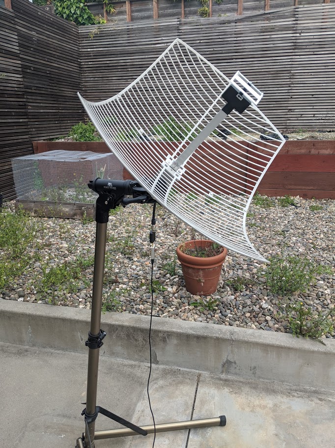
Aligned dish
The antenna I bought was a 2.4GHz antenna intended for extending WiFi coverage. Since the signal from GOES-17 is 1.6941 GHz, there is a common modification that people have been doing to tune the antenna closer to this frequency. The modification is either to flip the reflector around, or install a small spacer between the reflector and the feed. I opted for a ~2.5cm spacer. This is a bit of a hack since the dipoles in the feed are still tuned for 2.4GHz, but it is enough to work.
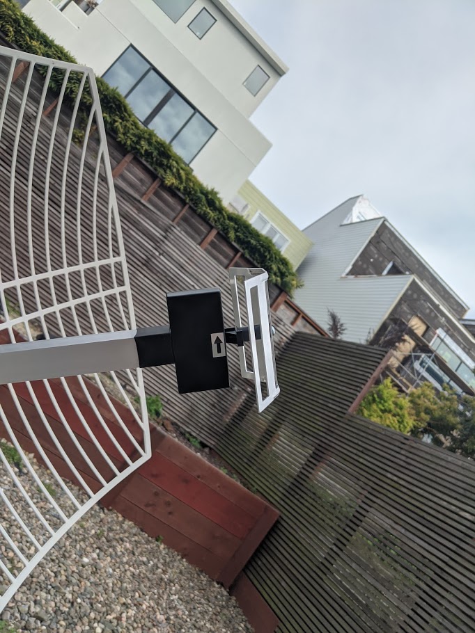
Spacer installed to tune antenna closer to 1.7GHz (from 2.4GHz)
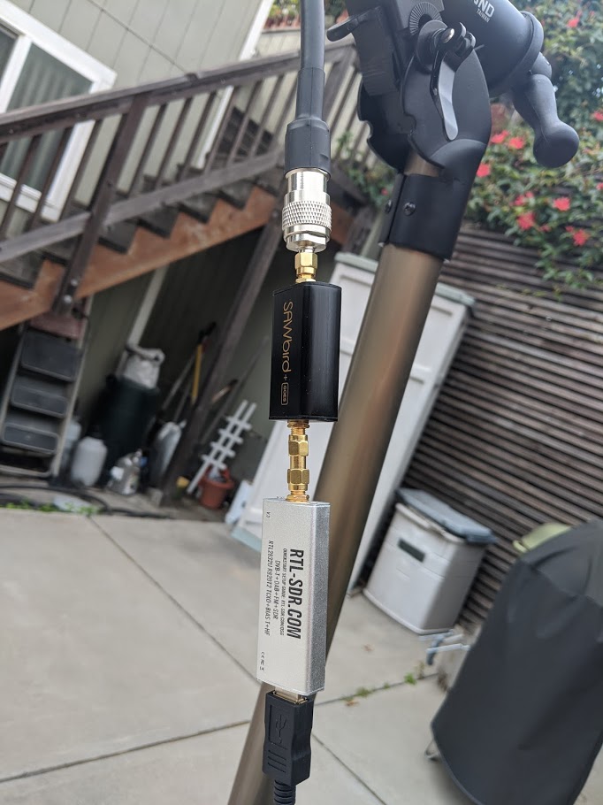
Then I connected up my low noise amplifier/filter combo from Nooelec, and connected it to my SDR. The LNA would be powered by the SDR which has a built in bias-t circuit to supply DC voltage.
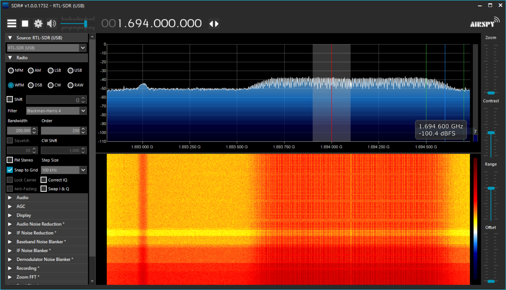
After a bit of toying around (a lot a bit to be honest… different spacer lengths, reflector layouts, antenna orientations, etc..)… I found the signal and it was coming in pretty clearly!
I then switched to Ubuntu and built/setup goestools. Goestools is a set of tools used to receive and decode the signal from the GOES satellite. Once I configured goestools to enable the bias-t on my sdr to provide power to the LNA, I fired it up and started adjusted the antenna slightly to try and minimize the viterbi error and minimize packet drops.
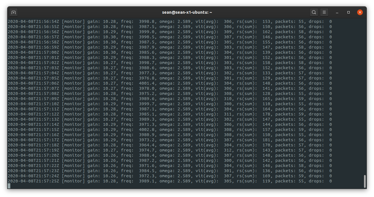
Once this was done, I then started up goesproc and it started processing data and saving images!
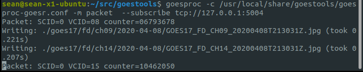
Here is the first thing that came in!

Since this satellite is geostationary…I was done! I left it running for ~24 hours and stitched together the images using ImageMagick to make some nice gifs.
GOES-17
GOES satellites have a few imagers and some can be requested by government agencies to point at specific things for certain reasons, these 2 gifs/sets of images are 2 additional images that get produced.
GOES-17 M1, changed where it was pointing part of the way through
GOES-17 M2
You can read about what it is pointed at and why here at the NOAA message list.
The GOES satellites also have a relay system where they relay smaller images from a few other similar satellites.
NOAA GOES-16
Japanese Himawari-8
I also received some National Weather Service data from the satellite…
Reading more about this specific satellite (GOES-17), it has definitely had some problems. Most notable was GOES-17 ABI cooling failure which lead to them running reduced hours at different parts of the year to prevent the images from being over-saturated due to overheating.